Sziasztok! Szeretném megtudni, hogy az A4988 bipoláris vezérlőt, ha 16-od mikrosteppel használom, milyen gyors legyen a STEP jel. Mennyi legyen a jel hossza és a két magas állapot közti szünet hossza. Közönöm.
Törölt felhasználó
2021-04-27 20:02:04
[1929]
Jobban preferálom a wmwaret legvalosabb a hadweres szimulácioja ez a funkció vissza álitja alaphelyzetre amit beálitotál honan induljon az adot rendszer... Erösen ajánlot az ssdröl... vmware non persistent disk
Modult telepiteted nem kell mindig max uj winfosnál csak... De nehéz kiszedni teljesen ami beépült regedit,user map,data folderekböl ... Más.. W10 ami frisitős verzios az teljesen felborit mindent mert direkt fejlesztős környezetre LTSC verziot használnak .... De ajánlom a virtuális oprendszer (virtualbox,wmvare) alatti kisérletézeket ott alap helyzetbe vissza álitható az oprendszer ahonan inditod ha be van álitva ez a funkció igy végtelen probálkozások száma ...
Az az átkozott "kisördög" csak piszkálódik! Ha újra megpróbálkozok ezekkel a parancsokkal, és újra nem működik, akkor mennyi esélyem lehet a mostani állapot visszaállítására?
Open source szinte mindig ráfizetés forrás vagy motor (környezet) szinte mindig van verzios kiadási problémák és csak néha időhuzás lesz belöle ... Fejlesztöi szintü emberkék kérdezve küzdenek a fenti problémákal forumokon jól is látszik...
Nos én is ezzel kezdtem! Mert ezt megtaláltam én is. De a tegnap esti képernyőkép készítése óta működik!!! Lefuttattam egy pár soros kis kódocskát legalább 10x és nem állt le, nem fagyott meg!!! Lehet, hogy elkiabálom, de úgy tűnik hogy MŰKÖDIK! Vagy csak megijedt a konkurenciától, mert már a Mach3-at is feltelepítettem mérgemben.
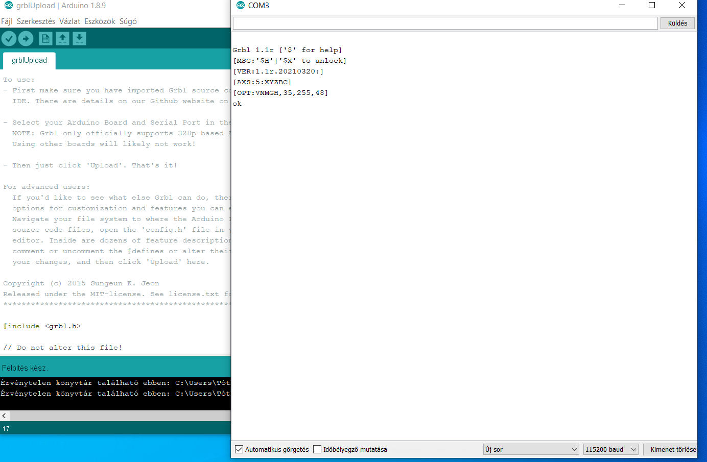
Microsoft Windows [Version 10.0.19042.928] (c) Microsoft Corporation. Minden jog fenntartva.
C:\Windows\system32>pip install python3 python3-pyqt5 python3-serial ERROR: Could not find a version that satisfies the requirement python3 (from versions: none) ERROR: No matching distribution found for python3 WARNING: You are using pip version 20.2.3; however, version 21.1 is available. You should consider upgrading via the 'c:\users\arany\appdata\local\programs\python\python39\python.exe -m pip install --upgrade pip' command.
C:\Windows\system32>'get' is not recognized as an internal or external command, ''get'' is not recognized as an internal or external command, operable program or batch file.
Ez meg a fordítás:
C: \ Windows \ system32> 'get' nem ismerhető fel belső vagy külső parancsként, '' get '' nem ismerhető fel belső vagy külső parancsként, működőképes program vagy kötegelt fájl.
Egy ilyen megoldja a problémádat... Fö probléma pc gnd és a védöföld közös ponton van (asztali pc táp ilyen) ahol a zavar bemegy motorok gerjesztése miat az usb busz részén adat hibákat okoz mert ott is jelen van... teljes elszigetelés kell csinálni fenti eszköz megoldja!
Biztos tök rossz értékek a dos os pc hez képest. (Ja ehhez is kell dos vagy win98 hogy összerakd) Ja mégse rossz, nem kezeli a robsy dos alatt lpt portról a +-10V jelet, meg 3 mérőlécet vagy encodert...Hát az csak egy vezérlő, ez meg szabályzó(mégha vezérlőnek is hívjuk). Step dir es világon túl is van élet.
Ilyenkor eltűnnek a forgó tengelyek (meg sem jelennek a képernyőn). Széthúzom-összedugom-újra indítom stb. és vagy visszajönnek vagy nem. Mi lehet az oka???
Hát mostanra nagyon megköszönném!!! Ez az egész egy eléggé szívatós dolognak tűnik. Tegnap találtam egy 6 tengelyes verziót. Kicsit "öregecske", de hát én sem vagyok már fiatal! Minden jónak tűnt, de amikor néhány futtatás után IDE segítségével változtatni akartam a beállításokon, megint "megdöglött". És ez így megy minden verziónál, amiket összeszedtem! Beállítás változtatása=káromkodás! Én vagyok a balf..., vagy ez tényleg ennyire nyűgös dolog? A 3 tengelyesek Nano-n és Unon jól működnek.
Mindkét megoldás érdekelne! Egyszerre! Jó lenne tudnom hogy miért nem boldogultam? Email az adatlapomon látható.
Sziasztok! Szeretném az 5 tengelyes Grbl-t működtetni! Működik is. De A-B tengely helyett szeretném B-C tengelyként hasznosítani. Ha jól értem a fordításokat, ehhez át kellene neveznem a tengelyt és megváltoztatni a számát a CPU_Maps-ban. De valamit nagyon nem jól csinálok!!! Tudna valaki segíteni?
frob | 2266
2021-04-06 19:47:48
[1898]
mondjuk mert egy ezresbe se fáj? :D ennyiért vagy elviseled és vele élsz, hogy csak 260x tudod másodpercenként ki be kapcsolni a marómotort vagy nem :D
érdemes lenne kipróbálni mondjuk stm32 re fordított grbl vajon mit tudhat, csak úgy érdekességként...
Normális vezérlő ha találkozik egy kóddal (ami ráadásul csak egy 1 bites be/kikapcsolási utasítás), azt a lehető leggyorsabban értelmezi, és végrehajtja. Kár a lassúságát védened, hiszen teljesen közönbös, hogy ez a kimenet mit kapcsol (motort, vagy lézert, vagy akármit), majd a kapcsolt rendszer a rá jellemező időállandójával, átviteli függvényével megoldja a végrehajtást, nem a vezérlő dolga várni, vagy ha várni akar, akkor ez a megadható paraméter lehessen nulla közeli idő is (t < 1 us). Ennek a tesztnek tehát semmi köze ahhoz, mit kapcsolunk, ez csak a CNC vezérlő adatfeldolgozási képességét, gyorsaságát vizsgálja. Felmerül ugyanis az alapkérédés: ha már itt vacak egy vezérlőrendszer és jelentősen késlekedik, mit várhatunk akkor a kapcsolt teljes rendszer végeredményétől? Így nyugodtan mindenki a kedvenc vezérlőjét letesztelheti, hogy aztán megmagyarázza utólag (feladva természetesen az objektivitást), miért olyan tetű lassú, és ez miért elfogadható.
ez a két parancs a motor start stop nem néztem még, de ha jól tudom van külön a lézerhez olyan parancs ami az energiát pwm en keresztül állítja
ezzel csak arra akarok kilyukadni, mennyire életszerű hogy egy motort másodpercenként 263 szor kapcsolgatunk?
viszont minden bizonnyal a lézeres M parancs, már tudhat jobbat, pláne hogy ott van egy pwm freki amivel eleve kapcsolgat és annak kitöltésével állítódik a teljesítmény, bár a grbl által elérhető előtolások függvényében lehet a 263 kapcsolás is elégséges lenne, és a fentebb említett pwm frekit sem ismerem ( 1kHz rémlik) viszont ebben a módiban használva tuti jobb az eredmény mint a motor kimenet kapcsolgatása
Csak érdekességképpen: Robsy kérésére végrehajtottam egy tesztet az általa írt CNC teszt kóddal 'Arduino' téma, 1887. hozzászólás A kérdés az volt, hogy a GRBL1.1 CNC vezérlő szoftver milyen gyorsan képes kapcsolgatni az egyik kimenetét. A teszt során pár ezer be-ki kapcsolás lett végrehajtva (M3 és M5 parancs), és a mért össz időből kiszámítottam az egy be-ki kapcsoláshoz szükséges időt. A kódot lefuttattam PC-ről is, és SD kártyáról is a hozzá való kis távvezérlőjén keresztül. Az eredmények eltérőek lettek:
- USB kapcsolattal, Candle programmal küldve: 3.8 ms, ami 263.16 Hz - SD kártyáról végrehajtva: 13.2 ms, ami 75.72 Hz
Az Inkscape programot még nem használtam (meg más hasonló programot se), de megnéztem róla egy YouTube videót, és igen, azzal JPG-ből létre lehet hozni a G-code fájlt, és azt a Candle-ba beolvasva ráküldheted a CNC gépre.
Arra figyelj, hogy minden beállítást, mint pl. szerszám átmérő, vágási mélység, sebesség, stb. az Inkscape-ben kell beállítani, mert utána a Candle-vel már nem tudsz a G-kódban módosítani.
Illetve annyit lehet változtatni a Candle-vel, hogy ha kell, marás közben % skálán arányosan tudod lassítani vagy gyorsítani külön a megmunkálási sebességet, az üresjárati sebességet, vagy a marómotor sebességét.
Teszt környezetbe elindultak a motor tudtam vezérelni, eddig pipa, építem tovább a gépet. Még nem próbáltam de az a kérdés inskape-be megcsinálom grbl fájlt azt cadle-ba be tudom tölteni, vagy van vmi egyszerűbb megoldás egy jpg kép marására?
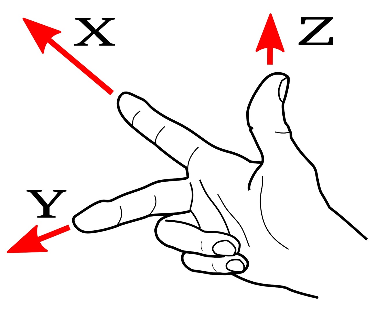
Köszönöm a félreértésem javítását. Én a kezet úgy láttam mintha pisztolyfogás lenne, mintha a mutató új előre, a középső új pedig balra mutatna, mert nekem ez lenne természetes fogás.
A második képet nem tudom miért értettem rosszul (kevés kávét ittam...?), mert abban igazad van, az logikus, az én gépem is így van, csak nekem az asztal +Y és -Y között mozog, mivel az X hídon van.
Az első képen az ujjak jól vannak, csak más irányból nézed. Ha a helyére forgatod a kezet, akkor jó lesz.
A második képen minden jól van, de ez is átverős, mert X-nél és Y-nál asztal irányt ír: mivel az asztal mozog a főorsó relatív elmozdulása a megfelelő irányba fog mutatni.
GRBL leírás szerintem hibás, mert összekeveri Y-vel az X-et, legalább is ezen a képen szerintem rosszul, fordítva mutatja.
Így írja:
„you will need to make sure your machine is moving in the correct directions according to a Cartesian(XYZ) coordinate frame and satisfies the right-hand rule, as shown”
...de viszont én úgy tanultam a koordináta-rendszert hogy az X tengely előtted van, jobbra-balra paralel a testeddel, az Y tengely pedig tőled indul el vagy feléd jön. Szerintem a kép rossz, mert igazából az Y = X és az X = Y.
A másik hiba az hogy a Linux CNC képe is hibás, legalább is nekem úgy tűnik. Ott az XY jó, de viszont az "+X Table Direction" az rossz mert fordítva van, amit +X pozitívnak hív az szerintem -X negatív.
Ez teljesen mindegy ha a G-kód jól van írva erre, de nem lehet G-kódokat cserélgetni közöttünk...
Arról van mérési tapasztalatod, hogy egy ilyen GRBL USB CNC vezérlő mennyire gyorsan (1 másodperc alatti ki/bekapcsolások száma mennyi?) hajt végre egy lézer ki/bekapcsolási parancsot? Szívesen küldök neked egy teszt kódot, aminek a futási ideje alapján máris tudhatjuk egy adott CNC vezérlő ezen műszaki képességét, jellemzőjét. Ez pedig fontos minőségi jellemző, csak sokan nem is foglalkoznak vele.


 Így nyugodtan mindenki a kedvenc vezérlőjét letesztelheti, hogy aztán megmagyarázza utólag (feladva természetesen az objektivitást), miért olyan tetű lassú, és ez miért elfogadható.